Documentation / v1.0 / Software Model
From emss Framework - iRobot Create C++ Framework
You are here: Documentation / v1.0 / Software Model
[edit] Software Model
The software which essentially runs our emss robot is divided into different components which ultimately make up the emss Core, described in detail in Section 4.3. Interfacing applications, which create an instance of the Core and provide the necessary connections for user interaction, have been omitted from our model as they are irrelevant to the functionality of the framework.
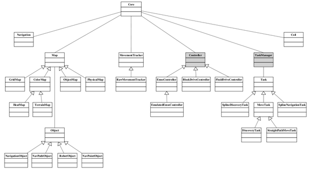
Figure 4-1 represents the final emss Core class structure. The Core class contains all the components, namely Navigation, Map, Movement Tracker, Controller, Task Manager, and COIL, and is responsible for instantiating them correctly in memory as well as de-allocating them. There are two running threads in the Core: Controller and Task Manager. The Task Manager is responsible for scheduling and executing Tasks, while the Controller is responsible for consequently communicating with the emss hardware. The design of separating Task execution and Controller execution produces a more robust controller, allowing certain logics such as cliff monitoring and emergency stops to be executed in a guaranteed fashion, even if a Task locks up and is no longer responding.
Our design has high transparency, allowing every component to “see” every other component, with one exception of COIL, which must only be accessed by the Controller. There are several lines of communication in the form of slots and signals21, the most important between the Controller and Movement Tracker, and between a Task and the Controller. In our design, all forms of action other than communication with hardware are realized through Tasks. While the Task Manager allows more than one instance of Task, only a single Task can be executed at once – part of the design to prevent multiple influences on the hardware communication interface. The Map and Movement Tracker components make up our data tier, assisting tasks in their job. Neatly packaging a set of functionally, the Navigation class also assists Tasks by providing navigational data structures such as splines and navigation points (way points).
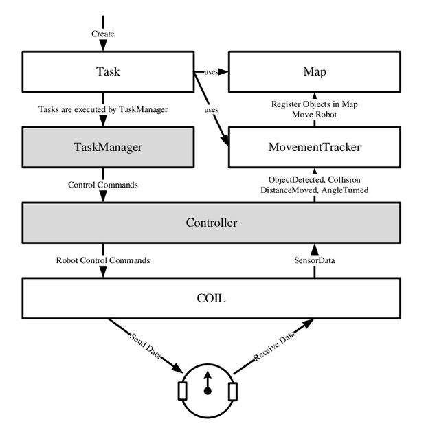
The model in Figure 4-2 shows the basic lines of communication in the emss Core. When a Task is created, and eventually executed, it uses the different Maps and the Movement Tracker as its data source. The Movement Tracker holds the current position and orientation of the robot, while the Maps contain information about the environment, such as obstacles or previous collisions. The Task Manager is responsible for executing the Tasks one by one. The Controller receives the control commands from the Tasks and forwards them to COIL. COIL produces a data packet and sends the command over a serial port to the iRobot Create controller. The robot interprets the commands and executes them directly on the hardware. Per request of the Controller, COIL reads sensor data from the iRobot Create controller, translates them, and forwards them back to the Controller. The Controller in turn interprets the sensor data and passes them along to the Movement Tracker and appropriate Maps. For further understanding how the Core components work with each other, we present two scenarios in Section 4.2.1 and 4.2.2.
The model in Figure 4-2 shows the basic lines of communication in the emss Core. When a Task is created, and eventually executed, it uses the different Maps and the Movement Tracker as its data source. The Movement Tracker holds the current position and orientation of the robot, while the Maps contain information about the environment, such as obstacles or previous collisions. The Task Manager is responsible for executing the Tasks one by one. The Controller receives the control commands from the Tasks and forwards them to COIL. COIL produces a data packet and sends the command over a serial port to the iRobot Create controller. The robot interprets the commands and executes them directly on the hardware. Per request of the Controller, COIL reads sensor data from the iRobot Create controller, translates them, and forwards them back to the Controller. The Controller in turn interprets the sensor data and passes them along to the Movement Tracker and appropriate Maps. For further understanding how the Core components work with each other, we present two scenarios in Section 4.2.1 and 4.2.2.
[edit] Fluid Drive Controller Scenario
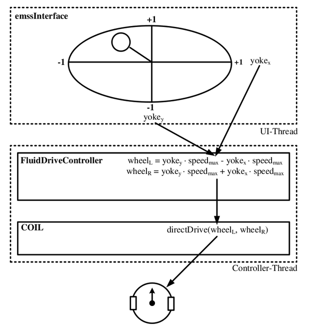
The Fluid Drive Controller is a simple Core Controller which can control the robots movement by joystick. Its details can be found in Section 4.3.3.2. The emss Interface includes a joystick widget which sends the position of the x-yoke and the y-yoke upon change to the Fluid Drive Controller. In turn the Controller continuously calculates the left and right wheel speeds, based on the yoke positions, and forwards them to COIL, ultimately sending the movement commands to the iRobot Create controller.
[edit] Emss Controller Scenario
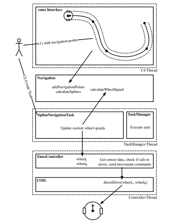
The Emss Controller scenario, visualized in Figure 4-4, uses the Navigation component and is slightly more complex. First an actor must set navigation points where the robot should pass through. This could come from either the graphical user interface or another Task. When these points are added, the Navigation component stores them and automatically creates the correlating splines for each wheel.
Furthermore, a Spline Navigation Task, which is executed by the Task Manager, will extract the needed wheel speeds from the Navigation splines and forward them to the Controller. Finally, the Emss Controller may “choose” to send the movement commands through COIL to the robot hardware, given that the action is deemed safe, et cetera.


